3 Bit Multiplier Circuit Diagram
Multiplier verilog adders Multiplier bit using schematic logic circuit building digital circuitlab created stack Digital logic 4-bit multiplier/adder
How to Design Binary Multiplier Circuit | 2-bit, 3-bit, and 4-bit
Circuitverse bit multiplier binary Multiplier circuit logic binary circuits adders multipliers Multiplier bit adder using multiplication binary schematic 3x3 calculator circuit digital types electricaltechnology multipliers electronics given below
Circuit multiplier
Multiplier adder logic bit digital circuit gates two complement circuitsBlock circuit diagram of the 6×6 multiplier $66 : binary multiplier (3 * 3) bits [hindi]Collaborative learning: binary multiplier.
4 bit multiplier circuit diagram3-bit multiplier Solved problem 3: the given figure depicts a four-bitMultiplier multisim sommatore adder.

Multiplier bit array vlsi high multipliers diagram logic work they digital vedic but examples most other
Digital logicLogic gates Design a 2-bit multiplier circuit using 4:1 muxLogisim multiplier bit circuit help following error create test when.
Digital logicBit multiplier logic array using multipliers work they adders digital implementation draw different way Multiplier bit logic circuit works using threeCircuitverse multiplier.

Multiplier binary circuitverse
Implementation of 2-bit multiplier circuit using pass transistor logic3-bit x 3-bit multiplier cellular array Bit logic gates using binary input square two adders make even squarer questions stackMultiplier circuit.
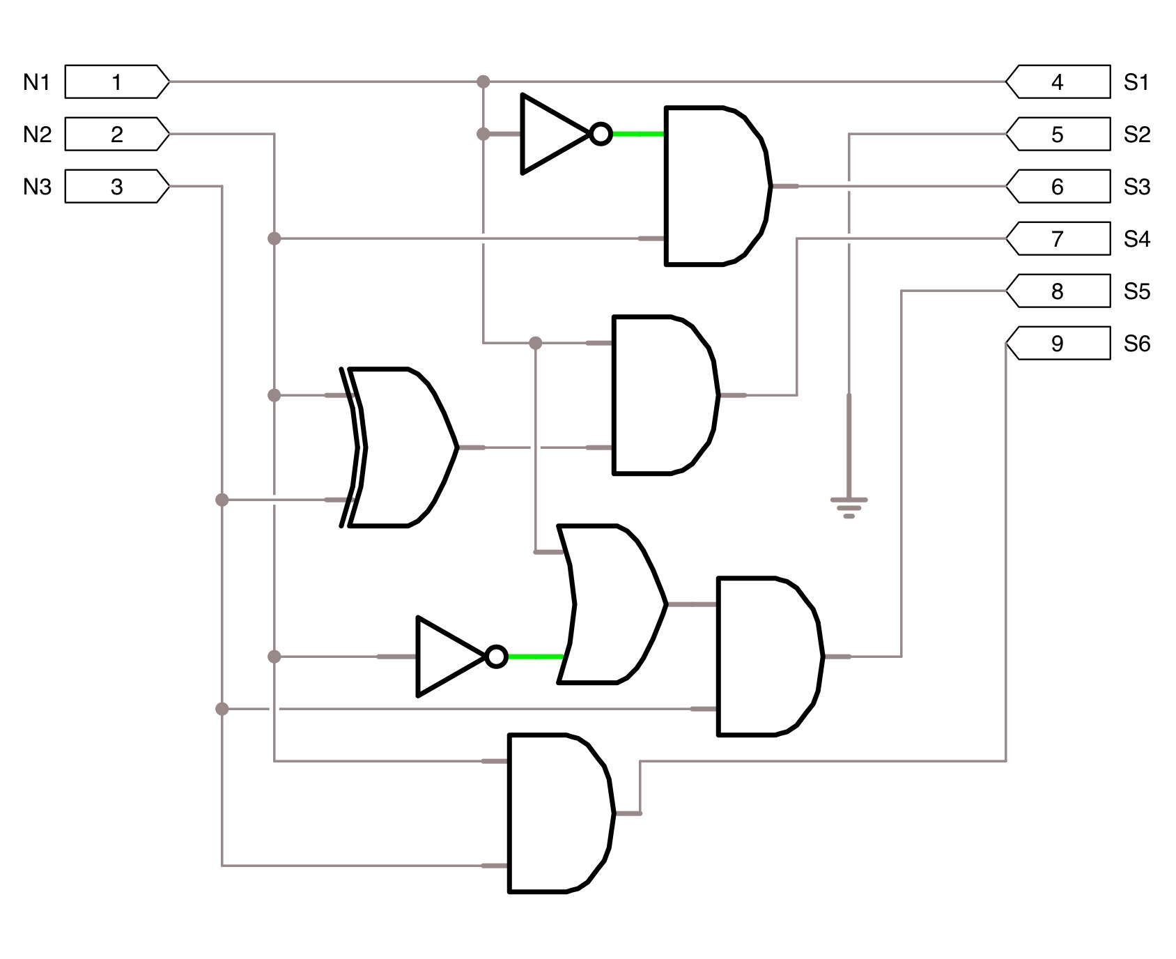
3-bit x 3-bit multiplier logic works designBinary multiplier Evolved 3-bits multiplier : 29 gates with 6 levels, using and, and withMultiplier using evolved inverted input xor.
Circuit design
Sommatore a 3 bitSquare 3 bit input using two 3 bit adders and logic gates 2 bit multiplier circuitMultiplier bit binary using multiplication adders schematic calculator divider 4x4 digital adder logic gates possible electricaltechnology build electronic electronics types.
Solved how can you modify the 2-bit by 2-bit binaryBlock circuit diagram of the 12×12-bit multiplier Multiplier binary circuits multiplication bits adders increases partial technobyteMultiplier circuitverse.

Bit adder number using circuit multiplying stack
Solved write the verilog module to describe the 4 x 3How to design binary multiplier circuit 1) the schematic below is the 4-bit multiplier shownBit multiplier array vlsi 3x3 hree three.
4 bit multiplier circuit diagramDigital logic Multiplier binary bit diagram collaborative learning algorithm figureCircuit design.

4 bit multiplier circuit diagram
.
.


Solved How can you modify the 2-bit by 2-bit binary | Chegg.com

Implementation of 2-bit Multiplier Circuit Using Pass Transistor Logic

1) The schematic below is the 4-bit multiplier shown | Chegg.com

Multiplier - Designing of 2-bit and 3-bit binary multiplier circuits

Solved Problem 3: The given figure depicts a four-bit | Chegg.com

4 Bit Multiplier Circuit Diagram - Diagram Circuit