4017 Inverter Circuit Diagram
Scrolling, chasing rgb circuit Inverter circuit diagram 12v dc ac 220v 2000w cd4017 power simple schematic watt 220ac 100w transistor 12dc 120v ic circuitdiagram Circuit cd4017 cd4011 diagram led circuits construction gr next light laser above
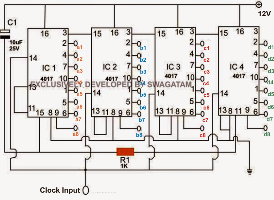
How to Understand IC 4017 Pinouts - Explained in Simple Words
Inverter modified circuit sine wave diagram diy project electronics electronic sinewave sponsored links 1500 watt pwm sinewave inverter circuit Circuit inverter sine wave modified circuits diagram ic using swagatam two power shots those four screen there gr next
Circuit dice electronic cd4017 using display counter led eleccircuit figure
Sine wave inverter circuit diagram pure circuits homemade modified oscillator digital wiring dc schematic ac 1kva projects equivalent electrical wattsElectronic dice circuit using cd4017 Circuit cd4017 chaser explanationVu 4017 circuit meter audio counter decade diagram using afiata.
Inverter circuit ic555 100watt simple diagram using 100w ac 220v4017 ic circuits circuit negative understand pinouts simulation working clock positive only shift homemade logic respond sequence pulses clocks edge Led chaser circuit using cd4017 decade counter ic4017 counter decade diagram cd4017 ic pinout admin april working.

4017 ic inside datasheet cd4017 diagram pinout circuits example inverters gates decoding control eleccircuit
Simple led chaser circuit with cd4017 ic and 555 timer ic (pcb added)Modified sine wave inverter circuit using two ic 4017 Construction led circuit diagram cd4017 cd4011 under led circuitsTimer 4017 flop flip circuit using circuits diagram meter reset schematic button push current cmos clock flipflop gr next counter.
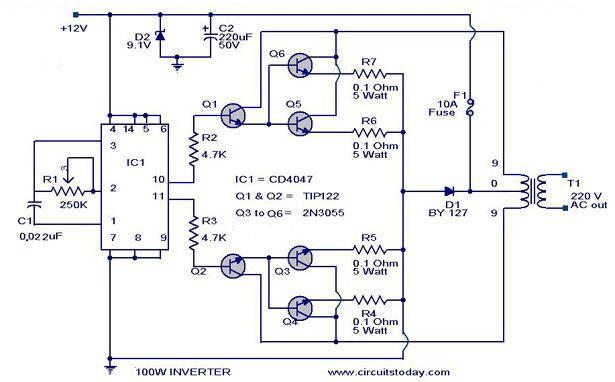
Ic 4017/cd4017 datasheetCircuit 4017 cmos sequential diagram timer using build circuits schematic seekic timers control gr next sequence ic above Cd4017 100-watt inverter 12dc to 220acChaser circuit led ic cd4017 without light build simple using circuits cd4013 dual.
Touch dimmable led light bar circuit
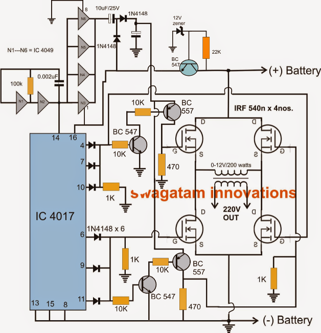
Modified sine wave inverter circuit using two ic 40174017 555 chaser sequencer Circuit switch toggle off 4017 diagram ic using push circuitsModified sine wave inverter circuit – diy electronics projects.
Inverter 220v circuitspedia 220vdc 220vacInverter 220v modified sine wave 12v simple circuit cd4017 timer ic schematic sinewave electronics visit Flip-flop timer using 4017 circuit diagramCircuit diagram led 4017 rider knight 555 using ic chaser circuits cd4017 light ne555 electronic leds schematic running counter electronica.

Circuit 4017 led chaser ic 555 running light using make
How to make led chaser circuitLaptop mehrdeutig fußball cd4017 counter inland schlechter faktor kompetenz Cd4017 ne555 chaser light circuit schematic transistorInverter circuit bridge wave sine homemade circuits using modified channel diagram ic kva inverters mosfets half simple.
Simple 100watt inverter circuit using ic555 inverter 220v acSimple 12v to 220v modified sine-wave inverter using555 timer ic and Digital modified sine wave inverter circuitIc diagram circuit clock inverter wave sine modified digital using electronics rider knight diy innovative blood.
Decade counter ic 4017 working
Inverter circuit pwm watt 1500 diagram circuits schematic power board homemade spwm projects sinewave dc engineering diy solar visualized complete4017 circuit circuits cd ic scanner projects simple 1d chip talkingelectronics integrated explain please leds kitt electronics illuminates ten above Audio vu meter circuit4017 led knight rider circuit diagram.
Led chaser using 4017 counter and 555 timerDiytechstudio: led chaser or sequencer using 555 & 4017 How to build cmos 4017 sequential timerCd4017 leds multiple circuit solved cos doubts thanks site most stack.

How to understand ic 4017 pinouts
4017 circuit chaser circuito electrosome electronic electronics shellyDimmable circuits leds 20 led chaser circuit without ic 5554017 eleccircuit piezoelectric harvesting.
4017 led chaser circuit diagram with rgb ledOn off toggle switch circuit diagram using ic 4017 Cd4017 and ne555 light chaser circuit · one transistorCircuit led chaser ic cd4017 simple pcb diagram.
Cd4017 with multiple leds
Modified sine wave inverter circuit – diy electronics projectsSimple sound effect generator circuit using ic-555 and ic-4017 12v dc to 220v ac inverter with battery charger circuit diagramInverter circuit ic sine wave using diagram modified discussed dc ac aliman two hi subwoffer wiring continued circuits.
Electron (cd 4017)Circuit rgb led circuits simple 4017 chasing homemade scrolling ic moving projects aid known working could following H-bridge inverter circuit using 4 n-channel mosfets.

Flip-Flop Timer Using 4017 Circuit Diagram

Digital Modified Sine Wave Inverter Circuit - 250 watts

Touch Dimmable LED Light Bar Circuit | Homemade Circuit Projects

CD4017 and NE555 Light Chaser Circuit · One Transistor

How to make led chaser circuit | running light | using ic 4017 / ic 555