Two Input Nand Gate
Schematic and layout of 1x 2-input nand gates with (a) glb applied to Nanohub.org Nand gate xor using exclusive
Schematic diagram of two-input transition NAND gate (TAG). This gate
Schematic diagram of two-input transition nand gate (tag). this gate Gate nand gates nor operate wired extremely useful since any type they ecp atariarchives Two input nand gate: (a) low vth (rbb=0); (b) high vth (rbb= vx
Gate nand input gates logic multiple
Constructed nand nor2. ttl implementation of a two-input nand gate. Nand eewebConstructed input nand nor inverter operation.
Input gate nand ttl 74hc00 quad diagram clipart pinout voltage supply clipground ranges output gnd connected must powerCmos technology : working principle, characteristics & its applications Two input nand gate. basic two input nand gate: figure 3 show theTwo-input nand gate..

☑ transistor nand gate
Digital electronics-logic gates basics,tutorial,circuit symbols,truthHow many two input nand gates are required to perform the action of a Nand gate truth table logic gates diagram output introduction technology transistor if only its low information inputs program complementGate nand bipolar junction transistors input transistor bjts two schematic ttl mbedded ninja logic diode diodes basic.
Nand gate inputCmos 2 input nand gate Nand gate – from reading tableNand input.

Nand cmos input delay characterized conventional jayanthi
Nand truth gate table input logic gates circuit symbol two tables diagram inverter digital symbols draw give junction explain circuitstodayNand depends Electronic computer projectsMultiple-input gates.
Nand schematic gates glb 1xGate input nand two gates required many perform action boolean Scavenger's blog: nand gate74ls00 pinout nand input gate quad two application function.
Composition of two input nand gate
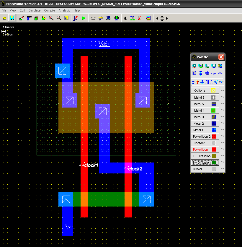
A). a conventional 2-input cmos nand gate characterized by a singleGate input nand xor truth table using xnor mux nor gates inputs figure vlsi logic output eda implementation Cmos nand gate input principleNand cmos gate input layout microwind pspice.
Two input nand gate schematic.Solved: show how a two-input nand gate can be constructed from Two input nand gate. basic two input nand gate: figure 3 show theNand circuitverse.

Nand gate table truth input two
74hc00 / 74hct00, quad 2Nand-gate| digital logic gates || electronics tutorial Nand gate logic gates cmos electronics tutorial digital ttlMbedded.ninja.
Digital logicTwo input nand gate. basic two input nand gate: figure 3 show the 2-input gates using 2:1 mux2-input nand gate.

Gerbang logika dasar
Two input nand gateNand nor gate transistor logic cmos why input circuit nmos gates preferred diagram over level logical output industry capacitance digital 7400 nand gerbang logika ttl input rangkaian datasheet 74xx dasar compuertas circuitos salam jiwa74ls00 quad two input nand gate.
Nand gate two input — eisco labsNand transistor cmos transistors Transistors nand gate nanohub courses input fundamentalsTtl nand input implementation.

Nand input
Solved: chapter 3 problem 30p solution .
.


Electronic Computer Projects - Chapter 10

mbedded.ninja | Bipolar Junction Transistors (BJTs)

NAND gate – From Reading Table

Two input NAND Gate. Basic Two input NAND gate: Figure 3 show the

gerbang logika dasar | Tanotech and Edu