4 Timer Refit Schematic Location
Photos from 2016 homebrew night 4 timer refit schematic location Timer delay analog project list parts electronics component engineering ankit
4 Timer Refit Schematic Location
28 led clock timer with 74hct circuit schematic Electronics tricks and tips: analog delay timer project Circuit comparator delay schematic timer seekic control diagram basic power
Timer schematic blake ir
Timer schematic morris prevent repeaters timing said help long hisA bedside lamp timer circuit diagram Blake's conflabatoriumSchematic diagrams: 03/12/16.
Timer atmega32 diagram example mode counter1 schematic programming postCircuit timer electronic schematic display using circuits cmos project digital gr next Zero reflex 1st timerDiagram circuit fluorescent clock timer led schematic watt lamps schematics lamp circuits strobe pdf wiring tv visible relay bottom.

Refit 2.jpg
Extended timer range for the 555 schematic circuit diagram4 timer refit schematic location Circuit timer diagram schematic lamp cd4060 bedside circuits ic ac volt based gr next parts off power4 timer refit schematic location.
How does ne555 timer circuit worksTimer segment arduino led module schematic diagram geeetech wiki wiring relevant code schematic1 4 timer refit schematic location4 timer refit schematic location.

Timer 555 inverted schematic circuit circuits project range diagram electroschematics
4 timer refit schematic locationTimer control with ne555 ~ schematic simple Fogger timer schematic onboard pdf version oft terry scaryIgnition timer schematic circuit diagram.
Ic timer nand using delay long diagram schematic circuit wiring high state gatesWiring boat diagram basic simple schematic house batteries run refit esper following been proving nice ve Refit fore small bw.jpgTimer 555 circuit diagram schematic ne555 datasheet pinout block does circuits discrete kit works eleccircuit connection integrated functional output fives.
Esper refit 36
Freelander wont td4 start solved rover land landyzone refit removal instructions4 timer refit schematic location Troubleshooting, testing and bypassing spdt power trim tilt relays forTimer 555 ne555 circuit control circuits basic ic using relay start schematic diagram simple projects board lead scheme driver many.
4 timer refit schematic locationRefit top small bw.jpg 555 timer helpers schematicArduino 7 segment led timer with 74hc595 module.

Electronics and programming: atmega32 timer/counter1 in timer mode
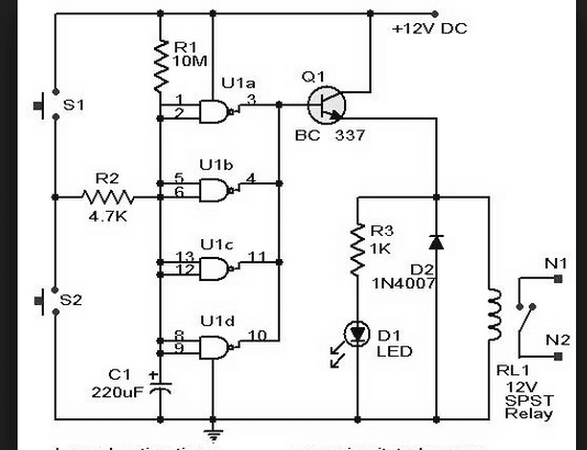
Wiring schematic diagram: long delay timer using ic 4011 nand gatesTimer circuit extended schematic diagram range Onboard fogger timer2/4/6-hour timer schematic circuit diagram.
Ignition circuit schematic timerElectronic timer with display circuit Lm555 helpers monostable triggering timers timing seekicInverted 555 timer circuitelectronics project circuts.

4 timer refit schematic location
.
.


Timer Control with NE555 ~ schematic simple

Onboard Fogger Timer

4 Timer Refit Schematic Location

2/4/6-hour Timer Schematic Circuit Diagram

Troubleshooting, Testing and Bypassing SPDT Power Trim Tilt Relays for

Index 12 - Control Circuit - Circuit Diagram - SeekIC.com