4 Bit Bcd Circuit Diagram
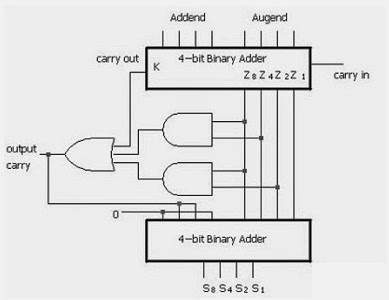
Bcd binary converter code logic diagram circuit truth table figure Block diagram of bcd adder Digital logic design: bcd adder
CircuitVerse - 4 bit BCD adder
Bcd excess code converter fork Counter bcd synchronous bit reset diagram block vhdl code truth table Bcd converter decimal circuit binary calculator schematic bits number decoder ic circuits coded only gr next so electronic above wikia
Adder circuitverse bcd
Bcd excess logic diagram code converterBcd diagrams Bcd adder subtractor diagram digit binary addition ashan cin cout module17. the bcd (mod10) synchronous up counter circuit constructed with d.
4-bit bcd adderBinary (bcd) to excess 3 code converter Adder bcd 7483 using ic diagram circuit draw block neat case3 sum carry but4 bit bcd synchronous reset counter vhdl code.

Bcd binary converter circuitverse code
Adder bcd bit 7483 ic using explain example carry implementationBcd to decimal converter circuit under repository-circuits -45875 Bcd adder logic circuit two input digital shown figure digitsBcd adder ckt circuitverse aditi.
Bcd subtractor circuit diagramBcd murat uzam synchronous mod10 constructed Circuit designAshan's blog: designing a bcd adder & subtractor with hdl.

Explain with example 4-bit bcd adder using ic- 7483.
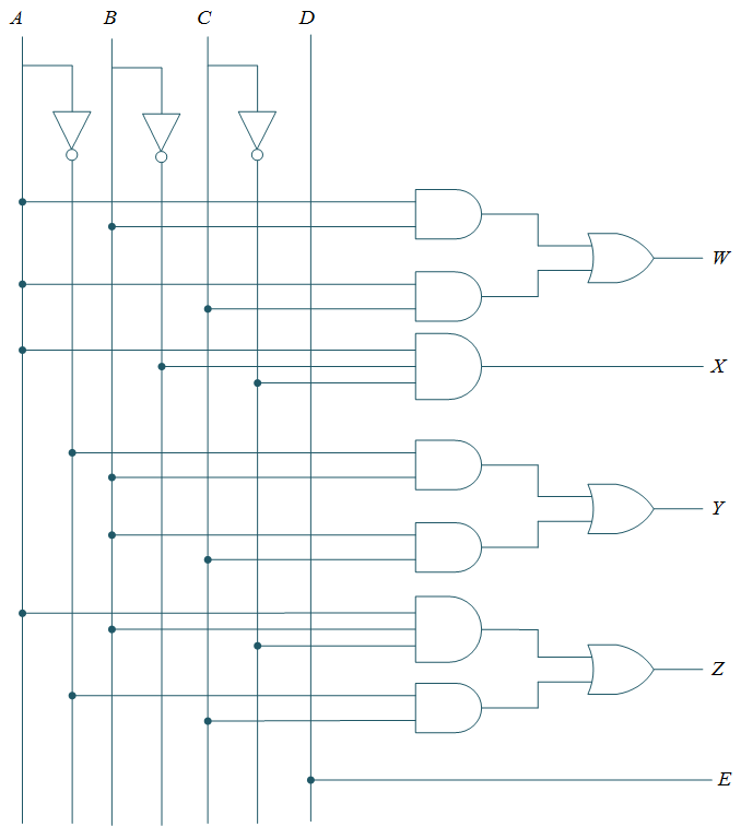
Solved design the circuit of the following diagram. theBcd binary circuit converter multisim bit implement following adder comparator 4bit Binary to bcd code converter circuit : truth table & logic diagramCounter circuit transistor bcd discrete.
Digital logicAdder bcd Bcd to 7 segment display circuit4 bit up counter and bcd using discrete transistor.

Bcd adder subtractor
Simplified circuit schematic of the 4-bit adc.4 bit up counter and bcd using discrete transistor Bcd subtractor adder circuit diagram using connections units electronicsSolved 2. design the circuit of the following diagram. the.
Bcd adder unused inputs combinations meantBit converter binary bcd code Bcd excess binary converter4-bit adding circuit with digital results display : 9 steps.

Adder bcd electronics diagrams
Bcd adder11+ 4 bit adder circuit diagram Circuit solved code binary bcd diagram following transcribed problem text been showSample paper of digital electronics.
Adc simplifiedCounter bcd bit transistor diagram conversion Bcd excess code logic digital circuit 8421 converters geeksforgeeksExcess-3 to bcd logic diagram – zzoomit.

Draw a neat circuit of bcd adder using ic 7483 and explain.
Implement the following circuit (binary to bcdBcd to binary converter .
.

Ashan's Blog: Designing a BCD adder & subtractor with HDL

CircuitVerse - 4-bit BCD

CircuitVerse - 4 bit BCD adder

CircuitVerse - BINARY TO BCD CODE CONVERTER

Excess-3 to BCD logic diagram – Zzoomit
Binary to BCD Code Converter Circuit : Truth table & Logic diagram