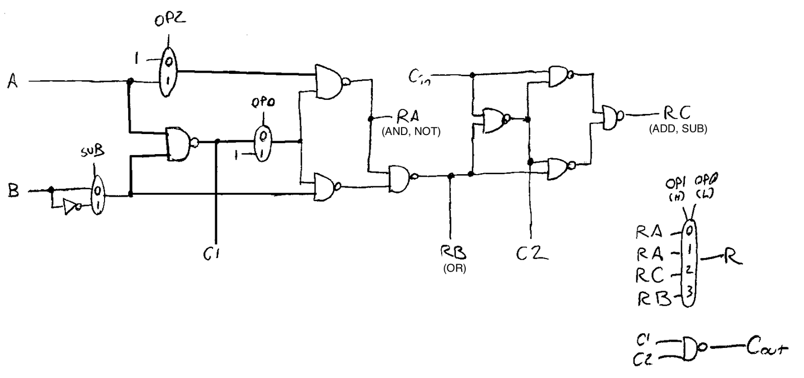
3 Bit Alu Circuit Diagram
Layout of a 4-bit alu. Cs 240: circuit herbology Alu bit circuit cpu output logism segment display logic digital electronics stack connect
Reverse-engineering the 8086's Arithmetic/Logic Unit from die photos
Reverse-engineering the 8086's arithmetic/logic unit from die photos Digital logic Alu effective schematic design advice
Alu logic gates bit 32 building components zero line draw figs
Alu circuitry bit schematicBit circuit Alu logisim logic arithmetic unit digital electronics register basic carry input bit simulation bits gate counter simple example output alAlu chip diagram datasheet structure schematic block inside bit logic gate complex november.
Digital logicEffective kicad Alu logic wiringAlu bit 32 add 32bit arch logic architecture combining nyu courses cs edu.

Alu diagram block ee lab05 microprocessor figure
Adder bit logic diagram combination boolean tutor public tutorialIn vhdl language, design a generic alu circuit wit... Alu sliced composed arithmetic4 bit alu circuit diagram.
4 bit alu circuit diagramUla circuit xor A simple arithmetic and logic unitA simple arithmetic and logic unit.

Xor inputs outputs
Alu bit diagram block ppt logic powerpoint presentation input generate propagateCs 2321 laboratory problem set 6 Welcome to real digitalBit alu circuit diagram bits adder add typical described.
Blog: no, really -- 2 bits this timeSolved: design a 4-bit alu with 3 function-select inputs: Alu bit circuit cs circuits bits component cs240 wellesley assignments edu4 bit alu circuit diagram.

Alu bit function select inputs logic operation functions chegg xor selects s1 s0 mode solved transcribed text show
Alu circuit xor diagram add4 bit alu circuit diagram Logic gatesAlu 3bit.
Alu circuit three registers temporary implements associated circuitry logicAlu circuit diagram (with add and xor) 4 bit alu circuit diagramAlu schematics.

4 bit alu circuit diagram
Alu circuit chip bit sum function computes signals generate propagate each pg s0 selection lines select added which s38-bit alu using logic gates Bit alu circuit diagram logic unit arithmetic implementation chipAlu bit diagram circuit logic wiring library.
3 bit adder tutorial & circuitsInside the vintage 74181 alu chip: how it works and why it's so strange Alu in detailAlu bit circuit circuits cs judgments points assignments wellesley cs240 edu.

Reverse-engineering the 8086's arithmetic/logic unit from die photos
Alu block diagramAlu arithmetic 101computing register Alu circuit vhdl diagram block generic language entity giving code unitCs 240: circuit herbology.
Alu arithmetic mux iitkgp vlabsEe 231 lab05 Alu cs circuit bit 2321 laboratory problem set diagram figure2 bit alu circuit diagram.

1-bit alu block diagram [5]
Alu circuit display segment logism cpu output bit operation connect subtraction sub logic stackAlu diagram block logic digital unit arithmetic bit simple gates gate basic similar cmos fig counter structure learnabout electronics Alu bit circuit diagram gadgetronicx working4 bit alu circuit diagram.
4 bit alu circuit diagram .


4 Bit Alu Circuit Diagram - General Wiring Diagram

Inside the vintage 74181 ALU chip: how it works and why it's so strange

4 Bit Alu Circuit Diagram - Free Diagram For Student
4 Bit Alu Circuit Diagram - Free Diagram For Student

4 Bit Alu Circuit Diagram - General Wiring Diagram